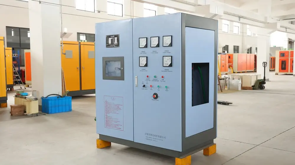
KGPS Technology Working principle
Control circuit principle
The entire control circuit, except for the inverter’s final trigger unit, is made of a printed circuit board structure.
The functions include power supply, rectifier trigger, regulator, inverter, startup calculation, vân vân. Except for the regulator, which is an analog operation circuit, the rest are digital circuits.
The core integrated circuit that makes up the control panel is IC6, model ASIC-330. It is a programmed special-purpose digital integrated circuit with 3 clock input ports and 31 input/output ports. Its internal functions include rectification and phase-shift triggering, phase sequence adaptive, inverter trigger, inverter lead angle lock, inverter repeated start, over-current protection, over-voltage protection, phase loss protection, low water pressure protection, control panel under-voltage protection, and three other 0.2-second timer.
Rectification trigger working principle
The three-phase synchronization signal is directly obtained from the three-phase incoming line of the main circuit through the gate leads K4, K6, and K2 of the thyristor. It is filtered and phase-shifted by R3, C1, R7, C2, R11, and C3, and then passes through 6 photoelectric The coupler performs potential isolation and obtains six rectangular wave synchronization signals (low level active) with a phase difference of 60 degrees and a duty cycle slightly less than 50%, which are input to 5P~10P of IC6.
This part of the circuit includes three-phase synchronization, phase sequence adaptive, voltage-controlled clock, digital trigger, final drive and other circuits.
There is a phase sequence adaptive circuit inside IC6, which ensures that the three-phase AC input of the constant power intermediate frequency power supply can be regardless of phase sequence. The characteristic of digital triggering is to use the method of counting (clock pulses) to achieve phase shifting. Các 6 phase-shifting trigger pulses are all generated by IC6. IC2C, IC2D and their surrounding circuits form a fixed output pulse width circuit. After being amplified by the IC5 transistor array, the 6 phase-shifted trigger pulses drive the output of the pulse transformer.
It is worth mentioning that the pulse transformer uses a flyback working method.

Conditions of Use
KGPS type thyristor intermediate frequency power supply is a static frequency conversion device that uses thyristor components to convert industrial frequency three-phase AC power into intermediate frequency single-phase AC power. It is mainly used in induction heating, induction melting and other occasions that require intermediate frequency power supply.
The thyristor element is cooled with water, and its control system is composed of integrated circuits with stable and reliable performance. When starting up, it adopts an advanced zero-voltage method, which is relatively safe and convenient. It is easy to maintain and economical, and is especially suitable for metal melting, heating and heat treatment conditions.
(1) Environmental conditions and building facilities
- This equipment should be installed indoors where there is no severe vibration, no conductive dust, no corrosive gas, the temperature is no higher than 40°C, and the relative humidity is no more than 85%.
- The intermediate frequency power supply room should be equipped with measures to prevent insects, rats, and snakes, and should have exhaust ventilation equipment and fire-fighting equipment.
- The trench should have a waterproof cement structure, be paved with wooden boards or cement boards and have drainage equipment, with good ventilation and heat dissipation.
- The main shell of this power supply should be well grounded (grounded according to general low-voltage electrical equipment standards, and repeated grounding is allowed). There should be personal safety measures and electrical protective equipment.
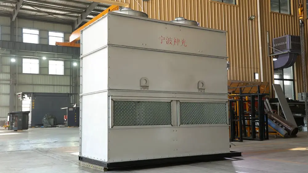
- When designing cooling equipment, a backup water source that can supply cooling water to the furnace should be considered when there is an external power outage.
(2) Requirements for cooling water
- PH value: 6~8
- Resistivity: 20kΩ/cm
- No sand or debris
- Inlet water temperature: 5~30℃
- Inlet water pressure: 0.12~0.15Mpa
- Water volume: 8 tons/hour
- The inner diameter of the outlet pipe is greater than 3 inches (open outlet pipe of the water tank)

Thông số kỹ thuật
The technical specifications of the intermediate frequency furnace are as follows:
- Equipment rated input: three-phase alternating current, Tính thường xuyên 50 Hz (60 Hz), line voltage 380 volts (high-voltage equipment includes 660V, 750V., 950V., 1050V., 1250V., 1450V., vân vân.).
- Equipment rated output: As shown in Table 1; under rated voltage or rated load, the output power can be adjusted smoothly and continuously, and the adjustment range is 5% – 100% of the rated power.
- It can prevent over-voltage during switch operation (such as QF switching, RS fuse, vân vân.).
- When the output voltage exceeds 1.1-1.2 times of the maximum output voltage or exceeds the voltage setting value, the overvoltage protection system will act, causing the device to automatically stop working and send out an alarm signal – lighting up the overvoltage indicator light in the instrument box.
- When the inverter bridge is short-circuited, the protection system will act immediately, causing the device to automatically shut down and send out an over-current indication signal – lighting up the over-current indicator light in the instrument box.
- If the output current exceeds the set value, the protection system will also automatically shut down the device and send out an overcurrent indication signal – lighting up the overcurrent indicator light in the instrument box.
- When the working pressure of the water cooling system is lower than a certain value, the machine can automatically stop and light up the water pressure indicator light on the panel.
- This machine is equipped with current limiting and voltage limiting links to limit the input current and output voltage within the set values.

---Ngày phát hành đầu tiên: Bước đều 21, 2024


